- experimental
- cfd
Vaporizer & Combustion Rig Design
An induction-heated tube vaporizer for MtG/ethanol surrogate fuel, sized against boiling glide, critical heat flux and flow instability, plus a fabrication-grade combustion-rig drawing package
datasheet // vaporizer-rigs
- images
- 7
- videos
- 0
- formats
- png
- text
- 982 words · 5 min read
- studio
- /atlas?ch=S53&ex=2
- source
- previous site
- topics
-
- analysis ×2
- tube sizing ×5
On this page0%
Problem
Feeding a liquid surrogate fuel — a methanol-to-gasoline (MtG) blend, 0–50 vol% ethanol — into an atmospheric non-premixed counterflow burner, a Bunsen burner and a smoke-point cell requires a vaporizer sized correctly for three coupled physical limits at once: boiling glide (the blend’s bubble and dew points shift as ethanol content changes), critical heat flux (push too hard and the boiling zone burns out), and flow instability (Ledinegg and density-wave oscillation). Get any one of them wrong and the rig either doesn’t vaporize cleanly or destabilizes under its own boiling dynamics — and because the same coil has to serve all nine blend ratios and the counterflow burner’s full strain-rate sweep, the design has to hold across a range, not just at one operating point.
Approach
Two vaporizer design generations, sized against a design flow of 10 mL/min and a wall-superheat target chosen so the inner wall clears a 180°C cap by 5 K and the bulk fluid clears a 145°C floor by at least 15 K, simultaneously, across every blend, incline angle, and the counterflow burner’s 50–200 s⁻¹ strain-rate sweep:
- v6 — a straight-tube atmospheric vaporizer with temperature-dependent real-gas fuel properties (PCHIP-interpolated, Peng–Robinson), full boiling-glide modeling (Liu–Winterton, Schlünder degradation, Katto–Ohno critical heat flux, drift-flux void fraction), and Ledinegg flow-instability checking.
- v7 — a pumpless, nitrogen-induction vaporizer design (40% fuel vapor / 60% N2, 180°C bulk limit), where the carrier gas itself does the pressure work.
The built coil (8 mm OD × 1.0 mm wall, 6 mm bore, SS316, 75° incline) runs 5.66 m for the longest blend (50 vol% ethanol) as four independently-fluxed stages — Preheat, Boil, Mist, Superheat — each running at whatever flux its own local heat-transfer mechanism supports, rather than one uniform flux for the whole tube. That staging is not a minor optimization: an audited comparison against a genuinely single, uniformly-heated zone shows the single-zone alternative needs 2.45–3.11× the length (7.30–17.57 m across the nine blends), because a single zone has to run at the flux of its most heat-transfer-limited stage (vapor superheat or, at the two highest-ethanol blends, mist) instead of letting the boiling zone carry a flux over an order of magnitude higher. Every rig dimension in the fabrication package — for this vaporizer and for the five combustion rigs it feeds (counterflow burner, soot/pool/Bunsen burners, a spray atomizer, an IC-engine injector rig, and a water-mist suppression rig) — is provenance-tagged (literature-derived, standard, or engineering-judgment-based), and DXF fabrication drawings are generated directly from the same parametric source.
Representative case: 6 mm ID / 8 mm OD tube
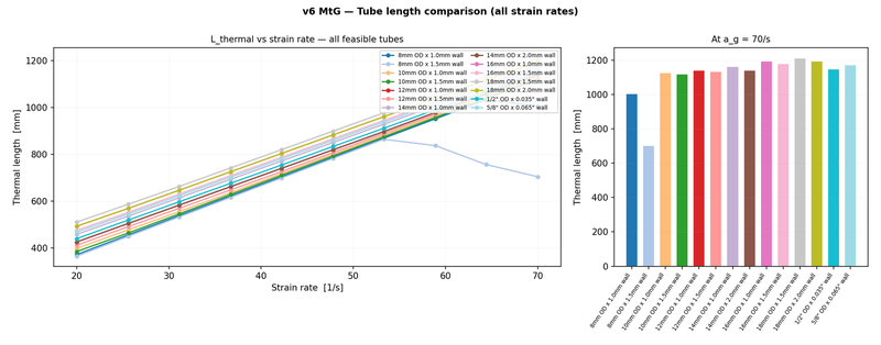
The built tube is one of 14 catalogue bores (5–15 mm ID) screened during sizing; a tornado sensitivity study found tube bore a secondary, non-monotonic lever on required length (shrinking the bore below 6 mm shortens the coil by up to 30% at the smallest catalogue bore before pressure drop starts pushing back), roughly 2.4× weaker than the wall-superheat design target itself. The gallery above shows this specific tube’s axial and radial temperature behavior across its strain-rate range: the four-zone structure — Preheat’s short sharp rise, Boil pinned at the 180°C wall ceiling while the fluid core stays at its dew-point plateau, Mist continuing at the ceiling, and Superheat carrying both wall and fluid core up together to the outlet — holds at both the low (20 s⁻¹) and high (70 s⁻¹) ends of the sweep, and the radial profiles confirm the wall’s own conduction resistance stays small next to the fluid-side film resistance in every zone. This same tube-bore screening flagged the 6 mm-ID case as falling in a dynamically-unstable (density-wave-oscillation) flow classification even though it clears the static Ledinegg stability check with a wide margin — a finding the fabrication-grade sizing report below independently reaches the same way: a static stability check does not rule out the dynamic mode, and it’s worth watching for on the built rig.
Commissioning & verification
Everything in the sizing model above is a prediction — correlations, property tables, an energy balance — not a measurement. The commissioning protocol turns those predicted curves into pass/fail acceptance criteria, checked against the report’s own model rather than an externally assumed tolerance: the fuel-coil’s six-zone axial temperature profile must track its predicted curve within ±10°C at every point (independently backed by a 175°C hardwired trip switch, not just the PID loop); bulk-fluid exit temperature at 160 ± 5°C; dew-point margin at the mixed-stream exit no narrower than a 20 K design floor; nitrogen-preheater outlet at 300 ± 15°C; wall temperature never above the 180°C cap; and fuel flow steady within 5% of setpoint. Commissioning proceeds in stages — thermocouple continuity and cold-junction checks, nitrogen-only heat-up, neat-MtG wet commissioning at design flow, a step-wise blend ramp to 50% ethanol, then a flow-rate transition down to the syringe pump’s actual 8–10 mL/h experimental rate — with the same hardwired trip chain (independent of the PID loop) armed from the very first nitrogen-only step onward, not a looser commissioning-mode configuration.
Validation
Twelve automated safety and sanity checks (v7/tests/test_v7_sanity.py) plus centralized constraint aggregation across every subsystem before a design is released for fabrication, on top of the physics-based verification above: the 180°C wall cap and 145°C bulk-fluid floor clear simultaneously at every one of the nine blend ratios, and required coil length stays comfortably inside the 5.76 m built (developed) length across the entire strain-rate sweep — no infeasible point occurs.
My contribution
Designed by me: the thermal-hydraulic sizing, the boiling-instability analysis, the tube-bore sensitivity study, and the DXF-generating parametric fabrication package. Physical fabrication of the rigs is outsourced; my role is design, specification, and commissioning oversight, not manual fabrication.
Where this is going
A vaporizer and burner rig set that goes from a parametric design study straight to a vendor-ready fabrication drawing, with every safety margin — thermal, static-stability, and dynamic-stability — checked and a pass/fail commissioning protocol written before a single part is cut.
Gallery
How to recreate this plot
Watch
Steps
- Open the controls panel
- Pick example 3: Heat loss through an insulated wall
- Set the outside air to -25 C
- Raise the inside air to 40 C
- Lower the outside film coefficient to 5
Code and PDF notes
Free of cost. I approve each request and reply by email.
To request the files, email me at krunalpanchal1995 [at] gmail [dot] com and mention the item id. project-vaporizer-rigs