- electronics
Sensors, MEMS and control
How tiny mechanical sensors work and how feedback makes systems behave - MEMS resonators, capacitive sensing and PID control. A first-principles learning page.
datasheet // sensors-mems-control
- images
- 2
- videos
- 0
- formats
- png
- text
- 590 words · 3 min read
- studio
- /studio (gallery)
- topics
-
- mems ×1
- control ×1
On this page0%
A learning page: standard theory from the textbooks listed at the bottom, with figures computed from the formulas shown. It makes no claim of new research results, and the parameters are illustrative.
Try it: the Bode filter instrument in Circuit Lab runs the formulas on this page.
Intuition
A MEMS sensor is a microscopic mechanical part, usually a small mass on springs etched into silicon, whose motion is read out electrically. Shake the chip and the mass lags behind; measure how far it lags and you have measured the acceleration. Control is the other half of the story: use the measurement to push the system back towards where you want it.
School level
- A mass on a spring bounces at a natural frequency f0 = (1 / 2π) √(k / m): stiffer springs and lighter masses ring faster.
- Friction (damping) makes the bouncing die away. Light damping gives a long ring; heavy damping gives a slow, sluggish return.
- Feedback: measure the output, compare it with the target, and act on the difference. A thermostat does this with heat.
College level
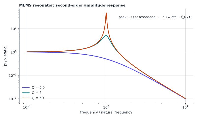
MEMS resonator. The mass-spring-damper has natural angular frequency ω0 = √(k / m) and quality factor Q = ω0 m / b. Its response to a force at frequency ω is flat at low frequency, peaks by a factor of about Q at ω0, then falls (figure 1). A high Q gives a narrow, sharp resonance, which makes small shifts easy to detect.
Accelerometer. Well below resonance the proof mass moves by x = a / ω02, so sensitivity grows as the resonant frequency falls, but bandwidth shrinks: a basic trade-off. Capacitive read-out uses C = ε A / d, so a displacement Δd changes the capacitance by ΔC / C ≈ Δd / d. The mechanical noise floor (Brownian motion) corresponds to an acceleration of about √(4 kB T ω0 / (m Q)) per root hertz, so heavier masses and higher Q give quieter sensors.
PID control. The controller output is u = Kp e + Ki ∫ e dt + Kd de/dt, with e the error. For the plant G(s) = 1 / (s + 1)3 in figure 2:
- Proportional only (Kp = 2) settles at Kp / (1 + Kp) = 0.67 of the target, a steady-state error.
- Adding integral action removes that error, at the cost of overshoot and slower settling.
- Adding derivative action damps the overshoot.
Advanced
- Frequency-domain design (Bode and Nyquist plots, gain and phase margin) predicts stability before building anything.
- Sensor fusion (for example, a Kalman filter combining a gyroscope with an accelerometer) beats any single sensor.
- Real controllers must handle noise, saturation of the actuator and integral wind-up.
Where this shows up
- Phone motion sensors, airbag accelerometers, gyroscopes in drones, pressure sensors.
- Motor drives, temperature controllers and cruise control.
Check yourself
- A resonator has Q = 50. By roughly what factor is the response at resonance larger than at DC? Answer: about 50.
- Why does a proportional-only controller on a plant with unit DC gain leave an error? Answer: it needs a non-zero error to produce any output; with gain Kp the loop settles where the output is Kp / (1 + Kp) of the target.
- An accelerometer’s natural frequency doubles. What happens to its low-frequency sensitivity a / ω02? Answer: it falls to one quarter.
Read next
- S. D. Senturia, Microsystem Design.
- K. J. Åström and R. M. Murray, Feedback Systems: An Introduction for Scientists and Engineers.
- G. F. Franklin, J. D. Powell and A. Emami-Naeini, Feedback Control of Dynamic Systems.