- electronics
RF, antennas and microwaves
Transmission lines, reflection and matching, antennas and the Friis link budget - how radio signals travel and how circuits hand them over. A first-principles learning page.
datasheet // rf-antennas-microwaves
- images
- 2
- videos
- 0
- formats
- png
- text
- 572 words · 3 min read
- studio
- /studio (gallery)
- topics
-
- links ×1
- matching ×1
On this page0%
A learning page: standard theory from the textbooks listed at the bottom, with figures computed from the formulas shown. It makes no claim of new research results.
Try it: the Smith chart and VSWR instrument in Circuit Lab runs the formulas on this page.
Intuition
At high frequency a wire is no longer just a wire. The signal is a wave that travels along it, and whenever the wave meets a change in the line (a connector, a different cable, an antenna) part of it bounces back. Radio engineering is the art of passing the wave from one place to the next without bouncing it, and then launching it into the air with an antenna.
School level
- Radio waves travel at the speed of light, so a 2.4 GHz signal has a wavelength λ = c / f of about 12.5 cm. Antenna sizes are a fraction of a wavelength, which is why Wi-Fi antennas are small and AM radio antennas are huge.
- A signal gets weaker as it spreads out over a bigger and bigger sphere. Double the distance and the received power falls to a quarter.
- Engineers use decibels: a loss of 3 dB is half the power, 10 dB is one tenth, 20 dB is one hundredth.
College level
Transmission lines. A line of characteristic impedance Z0 = √(L’ / C’) (inductance and capacitance per unit length) reflects a wave from a load ZL with
| Γ = (ZL − Z0) / (ZL + Z0), VSWR = (1 + | Γ | ) / (1 − | Γ | ), return loss = −20 log10 | Γ | dB. |
Only ZL = Z0 (commonly 50 Ω) absorbs everything (figure 2). Matching networks and the Smith chart are tools to bring a load to that condition.
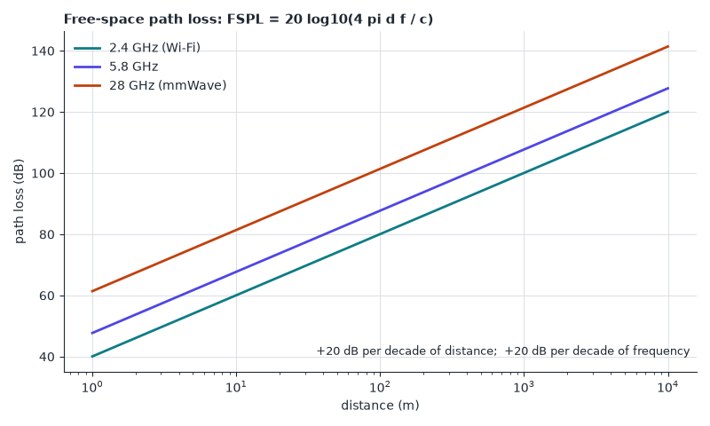
Free-space link (Friis). Received power is Pr = Pt Gt Gr (λ / 4π d)2, which in decibels includes a free-space path loss
FSPL = 20 log10(4π d f / c).
That is 40 dB at 1 m for 2.4 GHz, rising 20 dB for every tenfold increase in distance or frequency (figure 1). A half-wave dipole has a gain of about 2.15 dBi (directivity 1.64).
S-parameters. A circuit with several ports is described by how much of a wave incident on one port is reflected (S11) or transmitted to another (S21), measured with a vector network analyser.
Advanced
- Why millimetre-wave links (28 GHz and above) use arrays of antennas: the path loss is higher, so gain must be recovered with beam-forming.
- Noise figure, linearity and dynamic range of the receiver chain decide the real sensitivity of a radio.
- Waveguides, microstrip and coplanar lines are all transmission-line geometries with different loss and dispersion.
Where this shows up
- Wi-Fi, Bluetooth, 5G, satellite and radar.
- High-speed digital design, where board traces must be treated as transmission lines.
Check yourself
-
A 50 Ω line drives a 100 Ω load. What are Γ , VSWR and return loss? *Answer: Γ = 50/150 = 1/3, VSWR = 2, return loss ≈ 9.5 dB.* - How much more path loss does 28 GHz have than 2.4 GHz at the same distance? Answer: 20 log10(28 / 2.4) ≈ 21.3 dB.
- Why does received power fall by a factor of 4 when distance doubles? Answer: the same power spreads over a sphere whose area grows with d2.
Read next
- D. M. Pozar, Microwave Engineering.
- C. A. Balanis, Antenna Theory: Analysis and Design.
- T. S. Rappaport, Wireless Communications: Principles and Practice.